
Connect the RIGblaster Nomic to the FT-897 via the DATA port
Connecting your FT-897 to the West Mountain Radio RIGblaster Nomic for digital operationHere's the problem: I wanted to use my FT-897 on PSK31, SSTV and other digital modes, and wanted to use the RIGblaster Nomic due to it's small size. Unfortunately, hooking up the Nomic required me to unplug the radio's microphone as the Nomic has no microphone port (hence the name). After doing a bit of research, and contacting West Mountain Radio's excellent people, I determined that I could wire up an interface cable which would allow me to make all of my incoming and outgoing connections directly to the 897's DATA port. This allows me to keep the mic plugged in to the rig (which is GREAT when doing SSTV) and has the added bonus of letting me hear receive audio through the rig's speaker rather than messing around with an external speaker (too much stuff to carry around).
Disclaimer: This worked for me. It works for my FT-897 and it also worked with my FT-100D (before I sold it). It may not work for you. If you try this and you blow up your radio or anything else, or are hurt in any way, it's not my fault. This information is provided as-is and no warranties are made. You do this at your own risk. You'll have to excuse the drawings in the FIGs. They're a bit crude, but I'm not an artist.
Why the RIGblaster Nomic? A few reasons. Firstly, although I've built a few homebrew computer interfaces, I heard great things about the rigblaster products and decided to give them a try. I bought a RIGblaster Plus for my main station (an IC-746) and it worked great. Secondly, the Nomic is small and would pack nicely when I go out in the field. Third, I'm a hopeless gadget guy. I can't resist new gizmos and this one looked SO cool. You can definitely use the methods described here to connect different interfaces, but I'm writing up the one I have. Let me also say that my only relationship to West Mountain Radio is as a satisfied customer. So, on to the mad scientist stuff...
Parts:
You will need:
1 RJ-45 plug (Radio Shack makes one for use WITHOUT a special crimper)
1 length of CAT 5 network cable (length determined by your needs)
1 RS-232 9-pin Male to 9-pin Female serial cable (unless your PC has a 25-pinner on it in which case, get whichever one is appropriate)
1 RIGblaster Nomic interface box (with RJ45 "modular" jack).
1 6-pin DIN plug (male)
1 1/8" audio patch cable (stereo preferred, but mono should work, see FIGs)
1 1/8" audio plug (again, stereo preferred, but mono should do)
Building the interface cable:
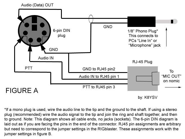
First, Please refer to FIGURE A. Here you will find a wiring diagram for this project. You will basically be building a "Y" cable. On one end will be the 6-pin DIN plug which will plug into the "DATA" jack on the radio. On the other end(s) will be an RJ45 plug (goes into the Nomic) and a 1/8" audio plug (goes to "LINE IN" on the PC). For clarification, the diagram shows a mono plug, but I used a stereo plug for mine. I just tied the ring and the shaft together and connected that to the GND line. In either case, the TIP has the audio signal on it. The GND (ground) lines are all tied to a common point on the DIN plug. The audio plug carries receive audio from the DATA jack on the rig to the LINE IN on the PC soundcard. Since you're not taking receive audio from the speaker jack on the rig, you will still be able to hear through the built-in speaker. Since all your data (incoming and outgoing) is coming / going through the DATA port on the rig, you will still have the use of your microphone and it can stay plugged in to the front of the radio. This is handy when you're sending SSTV as you can talk to the other parties between pictures.
Please be aware that the pin assignments I've chosen for the RJ45 (8-pin modular) plug are completely arbitrary, however, I've worked out the Nomic's jumper diagram (FIGURE B) to work with this configuration.
Notes on the RIGblaster Nomic:
The RIGblaster Nomic was designed to plug into a radio's microphone jack. Not being happy without stirring things up, I decided I didn't like that and set about changing it. Luckily, the folks at West Mountain Radio are good people and are quick to respond to questions. Since the Nomic is designed to feed audio from your computer into an amplified microphone-level input on your rig, the audio signal can be too low to properly drive the DATA IN line on the rig's DATA port. After an email to West Mountain Radio, I was directed to their website where they address this issue. The fix for this is to cut the "R2" resistor (100 Ohm) on the Nomic's mainboard. This effectively raises the audio output level from the Nomic to a level appropriate for the DATA port. Actually, I didn't cut mine, I broke out the soldering iron and lifted one leg of "R2" and then wrapped it in electrical tape to insulate it. I did this in case I ever wanted to put it back. Be aware that West Mountain Radio has not officially tested this and though they put it on their website, you're on your own with it.
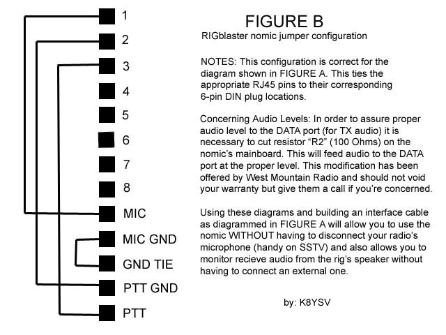
If you build the cable as is shown in FIGURE A, you should set the Nomic's internal jumpers as shown in FIGURE B.
Pin 1 to "MIC", pin 2 to "PTT GND", pin 3 to "PTT" and "MIC GND" to "GND TIE". Button everything up and proceed on to.....
Connecting everything:
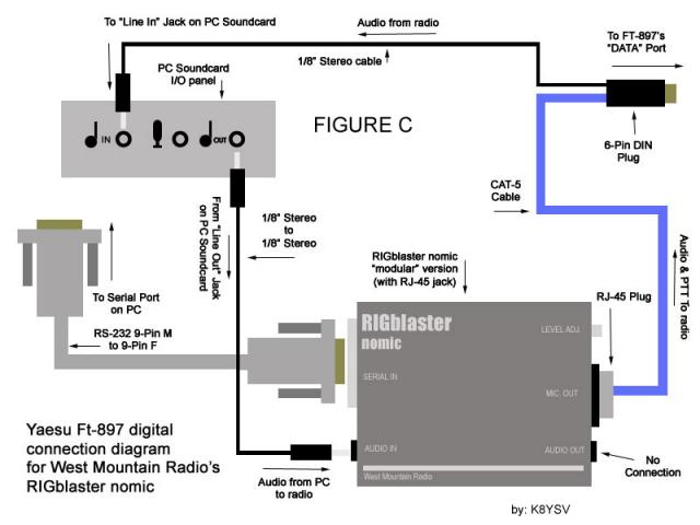
Please refer to FIGURE C. First, TURN OFF THE RADIO. Then plug the DIN end of your interface cable into the DATA jack on the rear panel of the rig. Plug the audio plug into your PC's LINE IN jack if you have one. If you have only a "Microphone" jack, you may use that, but you will need to adjust your mixer levels accordingly. Plug one end of the RS-232 cable into the PC's serial port, and the other end into the Nomic's "SERIAL IN" port. Lastly, run the audio patch cable from the PC's "LINE OUT" or "Headphone" jack (whichever you have) to the Nomic's "AUDIO IN" jack.
Note that the "AUDIO OUT" jack on the Nomic is NOT connected to anything. Carefully check the connections, turn any volume controls you may have DOWN and power on the PC and the radio.
You will need to adjust audio levels in your software and for your computer in order to assure proper operation and there are so many possible combinations that I won't go into detail on that here. I use WinPSKse for PSK31, MMSSTV for Slow Scan and MMTTY for RTTY and this interface works well for all. I'm running all this on a Toshiba P2 300 laptop with "LINE IN" and "HEADPHONE" jacks. I've left the digital drive setting in the 897 at the factory default of 50 and use the volume control on the laptop to regulate the power output from the rig (IE the higher the volume from the soundcard, the more wattage is put out from the rig). The volume knob on the rig has no affect on the audio going in to the computer, it merely functions as volume for the rig's speaker at this point. In fact, if the sound annoys you after time, you can even turn your rig volume all the way down without affecting your operating. The DATA port's audio line is fixed volume. You should use your Windows mixer to adjust the level of the audio coming into the PC.
You may need to adjust the mixer settings differently for different programs, and if you switch between programs often, this can be a pain. I've found a nifty little freeware utility that makes this so much easier. It's called QuickMix. It's by a gentleman named Martin Saxon and is available for download from http://www.msaxon.com/quickmix/
I use it a lot and love it. At this point you should be good to go!
Good luck with this and I hope to catch you "on the waterfall".
73 de Jeff K8YSV
Copyright 2003. Permission is granted to freely distribute this document and all original diagrams, as long as everything is distributed together and I get the credit as the author. RIGblaster and Nomic are trademarks of West Mountain Radio. All other items are the property of their respective companies.
Categories that this topic belongs to: RIGblaster Nomic