
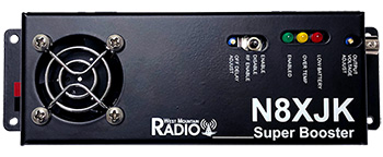
N8XJK Super Booster
#58515-1777
$249.95
- N8XJK Super Booster
- Owner's Manual
West Mountain Radio has collaborated with N8XJK to bring back the popular TG Electronics Booster! This unit will help you get the most life out of your battery.
This model is an improvement on a design that has been widely used in Amateur radio for more than 15 years.
The N8XJK Super Booster was specially designed for use with a radio.
When the voltage from a battery drops, the Super Booster brings it up to a level that allows for optimal transmit. The output level can be set by a trimmer pot to any value up to 15V. The advantage of using the Super Booster is that a Lead Acid battery is rated in Amp-Hours for use down to 10.5V. However, radios require at least 11.7V to transmit. That results in over one-third of amp-hours in the battery cannot be used for transmit without a booster.
For example, when doing 100W SSB with a 74AH battery (car size) allows for 10 hours continuous transmit. When using the Super Booster, the result is at least 15 hours of continuous transmit. Even at the last amp-hour of the battery's life, there is 10.5V and at least 11.7V to the radio. Transmitters tend to be more efficient at higher voltages, therefore there is additional savings by using, for example, 14.5V.

Note: This item is sold separately.
The Booster Remote control/monitor unit is a compact remote head that monitors input/output voltage, as well as error conditions like over-voltage and over heating.
Super Booster readily accommodates the remote control or to connect units in parallel to achieve 80A or 120A.
Capabilities
High Power
- Draws up to 40A from the battery
- Connect units in parallel for 80A and 120A
Quiet, Thermally Controlled Fan
- Allows for operation at max current continuously
Adjustable RF Enable Delay
- When RF input is used provides smooth transmissions
Other Great Features Include...
- Low voltage shut-off with LED indicator
- Extremely low RFI
- Switch for Boost, No Boost, or Auto when RF detected
- Optional Booster Remote control/monitor unit
Specifications
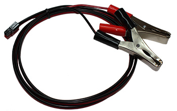
| Connectors | Anderson Powerpole®, 45A |
| Size | 8.0" x 2.3" x 2.2" |
| Weight | 16 oz. |
| Mounting Holes | Four - 0.175 d, #8 hardware |
Limits:
| Minimum Input Voltage | 9VDC |
| Maximum Input Voltage | 15VDC |
| Minimum Output Voltage | 9VDC |
| Maximum Output Voltage | 15VDC |
| Maximum Current | 40A Input (per unit) |
| RF Voltage Maximum | 100Vp-p (200W) |
Current Consumption:
| Power Off | 1.5mA |
| Standby | 24.4mA |
| Enabled Booster | 40mA |
| Low Battery/Overtemp | 39mA |
RF Enable:
| RF Detect Threshold | 3.3Vp-p typical. (0.22W) |
| RF "Turn On" Delay | 2ms typical |
| RF "Turn Off" Delay Range | 2-500ms typical |
Low Battery Lockout:
| Jumper Selectable | 9V, 9.5V, 10V, 10.5V, 11V, 11.5V, 12V |
| Voltage Drop When Booster Off | 0.76V at 20A load |
| Efficiency | Around 90% |
Temperature:
| Maximum Ambient Temperature (before shutdown): 32A Continuous Output |
110°F |
| Maximum Case Temperature (before shutdown): Sides Bottom Center Internal |
115°F 139°F 162°F |
Output Ripple:
| Load = 20A | (100W xmit) 4.2mV RMS, 12mVp-p |
| Load = 3A | (receive) 3.5mV RMS, 10mVp-p |
Quality Declaration
Product designed, tested and used by ham radio operators onsite.
Includes
- N8XJK Super Booster
- Owner's Manual


| Hardware | |||
|---|---|---|---|
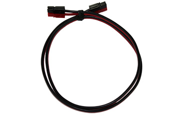
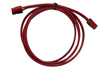
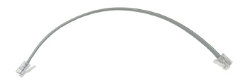 | Booster Parallel Cabling Kit 58515-1787 | $5.00 | Buy NowAdd to Wish List |
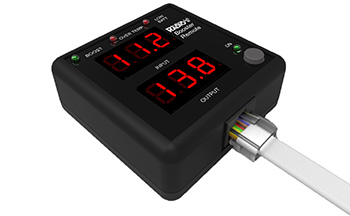 | Booster Remote 58515-1785 | $69.95 | More InfoAdd to Wish List |
 | Mounting Magnet 58515-1786 | $1.95 | Buy NowAdd to Wish List |
- Genderless Housings: Provide simplified assembly and minimize the number of components
- Stackable Modular Housings: Available in four sizes to right size your connection need
- Connection Versatility: Contacts for wire, PCB, or busbar all fit into the same housings
- Low Resistance Connection: Silver or tin plated contacts inside housings that strongly force the contacts together
- Color Coded Housings: Help ensure that connectors are assembled and mated correctly
- Self Securing Design: Stainless steel springs create a robust force between the contacts that holds the connector in the mated condition, but allows it to be quickly disconnected.
Anderson Powerpole® Connectors and General Installation Tips
| Powerpole® Connectors | |||
|---|---|---|---|
| 15A | 30A | 45A | |
| Amps (UL) Per Pole | 0 to 55 | 0 to 55 | 0 to 55 |
| Volts (UL) Per Pole | 600 | 600 | 600 |
| Amps Continuous | 15 | 30 | 45 |
| Wire Gauge (AWG) | 20 - 16 | 16 - 12 | 14 - 10 |
| Touchsafe Polarized Housing |
Yes Yes |
Yes Yes |
Yes Yes |
| PDF Files Links |
Data Sheet https://www.andersonpower.com/ |
||
| Buy Powerpole® Pack | View Options | ||