
Anderson Powerpole® Connectors and General Installation Tips
Powerpole® is a registered trademark of Anderson Power Products
Powerpole® Connector Features & Benefits
- Genderless Housings: Provide simplified assembly and minimize the number of components
- Stackable Modular Housings: Available in four sizes to right size your connection need
- Connection Versatility: Contacts for wire, PCB, or busbar all fit into the same housings
- Low Resistance Connection: Silver or tin plated contacts inside housings that strongly force the contacts together
- Color Coded Housings: Help ensure that connectors are assembled and mated correctly
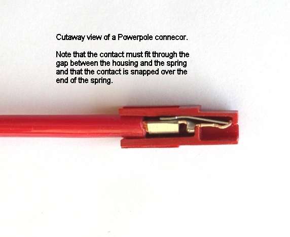
- Self Securing Design: Stainless steel springs create a robust force between the contacts that holds the connector in the mated condition, but allows it to be quickly disconnected.
| Powerpole® Connectors | |||
|---|---|---|---|
| 15A | 30A | 45A | |
| Amps (UL) Per Pole | 0 to 55 | 0 to 55 | 0 to 55 |
| Volts (UL) Per Pole | 600 | 600 | 600 |
| Amps Continuous | 15 | 30 | 45 |
| Wire Gauge (AWG) | 20 - 16 | 16 - 12 | 14 - 10 |
| Touchsafe Polarized Housing | Yes Yes | Yes Yes | Yes Yes |
| PDF Files Links | Data Sheet http://www.andersonpower.com/ | ||
| Buy Powerpole® Pack | View Options | ||
General Installation Tips
The following instructions are recommended for use with West Mountain Radio products and for ARES /RACES standard orientation. Note that you can assemble the red and black insulated housings in other ways for special applications.
1. Slide the connector housings together before putting the connector pins in, this is easier when using heavy paired wire. The plastic housings are held together with dovetail joints and are not meant to be snapped together/apart - this will cause damage.
Optional retention clips may be used to ensure the connectors do not separate when using heavy wire.
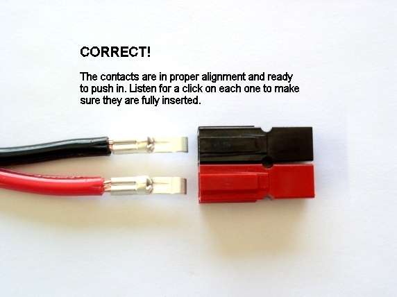
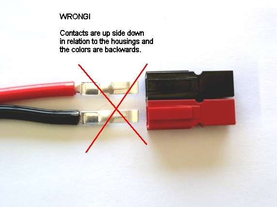
2. Before soldering or crimping the contacts on to heavy paired wire, orient the contacts to both face the correct direction and will go into the housings without twisting the wire.
Crimped Contact: A crimped contact contains the wire completely inside the pin and will not spread the connector apart. Check the recommended gauge(s) of wire for a contact. Use a crimp tool, such as the West Mountain Radio PWRcrimp, that will crimp the contact without being flattened. A properly crimped contact should have a minimum hold on the wire for more than 25 pounds.
Soldered Contact: When soldering the contact pins, be careful not to use too much solder. Keep the solder inside where the wire goes. Extra solder on the outside of the connector body may cause trouble putting the contact into the housing. If solder gets on the contact surface area, it may not make a good contact.
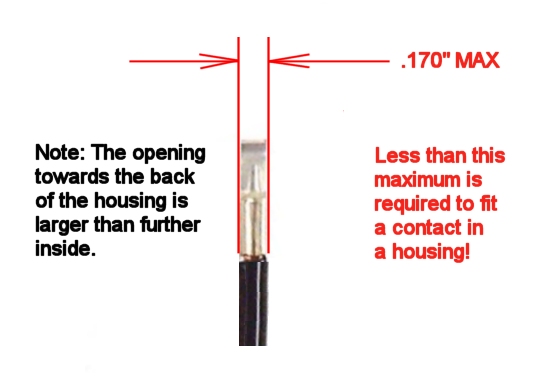
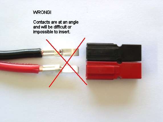
3. The contacts go in the housings in only one way. Insert the contacts with their sharp edge down against the flat spring that is in the housing. The contact should slide in and click, or they are not fully seated. When fully inserted, notice that the contact and its wire "floats" slightly inside its housing. If it feels tight it may not be snapped in fully or the contact may have been flattened out when crimped or soldered.
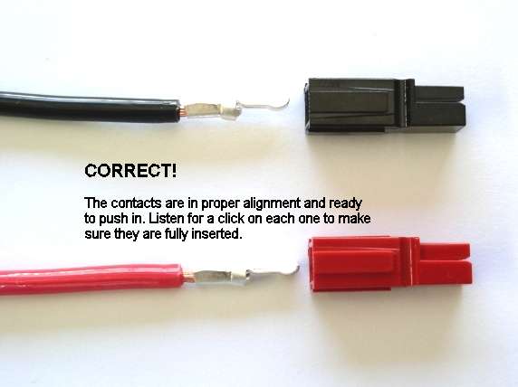
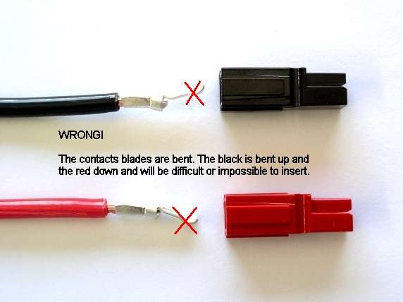
4. Tug slightly on the assembled connector to make sure the contacts are locked in place. If the contact does not lock into the housing, check to make sure the contact has not been widened or deformed. Look at the side profile of the contacts before and after crimping, as it may be necessary to bend it back straight before inserting it into the housing.
Click here to watch Powerpole® video tutorials.
Categories that this topic belongs to: TARGETuner, RIGrunners, DC Power Management